Adjustable pulse generator circuit under Oscillator Circuits Circuit Diagram
Adjustable pulse generator circuit under Oscillator Circuits Circuit Diagram These pulse generator circuits—a.k.a. an astable multivibrator oscillator circuit—employ a 555 timer IC, NE555 or LM555, in its astable (free-running) mode. These types of circuits are often paired up with digital logic circuits. The 555 timer IC is also very popular and simple to use, with a small eight-pin package and a supply voltage range of 4.5V to 16V.
Hello! For my very first instructable I wanted to show how to build a pulse generator circuit using the ever so popular 555 timer chip. This is a very simple, yet very important, circuit to build and understand. It provides a great introduction into integrated circuits and the 555 chip finds its way into many more sophisticated circuits.

Pulse Generator : 9 Steps (with Pictures) Circuit Diagram
This is sometimes called a one-shot circuit. The time it stays HIGH is decided by the size of a resistor and a capacitor. The higher the values, the longer it stays HIGH. If you connect a buzzer to the output, you can create an alarm circuit that is triggered for example by a window being opened. 555 Timer One-Shot Example Circuit A simple pulse generator can be designed with controller for input and output to an RC circuit. As it is well known that time constant of RC network can be fixed with suitable value of R and C. We need a input circuit that can charge the capacitor C and output circuit that can discharge the same capacitor.
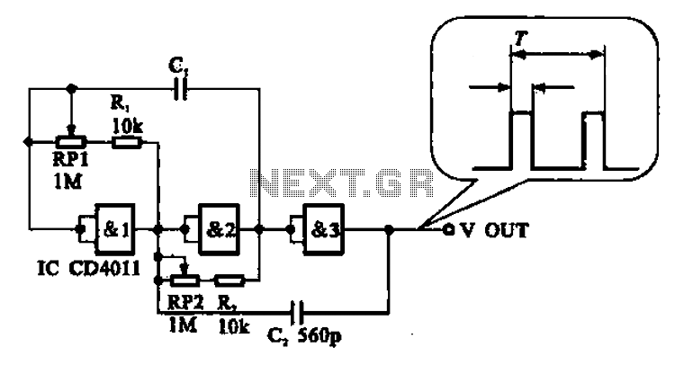
This is a pulse generator with adjustable duty cycle made with the 555 timer IC. The circuit is an astable multivibrator with a 50% pulse duty cycle. The difference from the standard design of a 555 timer is the resistance between pins 6 and 7 of the IC composed of P1, P2, R2, D1 and D2. The diodes D1 and D2 set a definite charging time for C1

How To Make Pulse Generator Using Circuit Diagram
How the Circuit Works. Any one of the total four gates can be used to produce an oscillator with a variable duty-cycle and a set frequency. The RC time-constant of this network that has a capacitor C1 and resistor R1+P1 helps in determining the pulse duration.
